tsci export
Overview
tsci export can be used to convert a tsx file or circuit.json file into
various output formats including schematics, PCB layouts, fabrication files, and more.
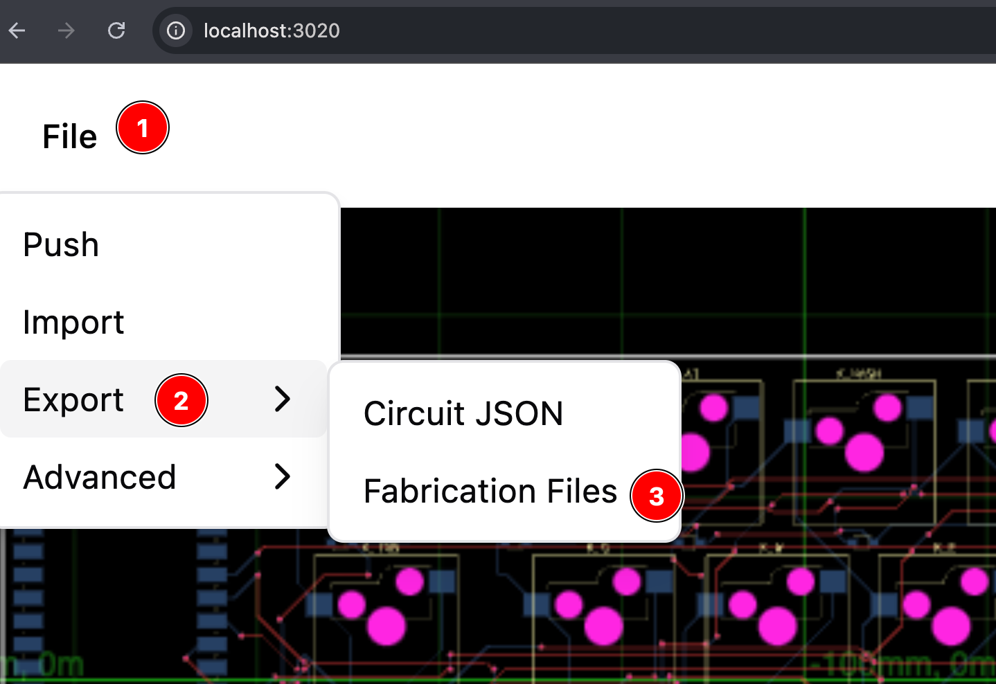
Usage
tsci export <file> [options]
Arguments
<file>: Path to the source file (.tsxor.circuit.json)
Options
-f, --format <format>: Output format (defaults to "json")-o, --output <path>: Custom output file path--drawing <name-or-filename>: Select a configured drawing page; implies--format drawing-svgwhen the format is omitted.--disable-parts-engine: Disable the parts engine during circuit evaluation--show-courtyards: Show courtyard outlines in PCB images--layer <layer>: Choosetoporbottom; during X-Ray, this layer is drawn in front--x-ray-net <name-or-id>: X-Ray a connected PCB net; repeat to select multiple nets--hidden-layer-opacity <opacity>: Opacity of other copper during X-Ray, from0to1(default:0.2)
Supported Formats
The following export formats are supported:
| Format | Description |
|---|---|
json | Circuit JSON format (alias for circuit-json) |
circuit-json | Circuit JSON format |
srj | Simple Route JSON for inspecting or sharing PCB routing input |
schematic-svg | Schematic view as SVG |
pcb-svg | PCB layout as SVG |
pcb-png | PCB layout as PNG |
assembly-svg | Assembly view as SVG |
drawing-svg | One configured assembly drawing sheet, including its part views and title block |
gerbers | Gerber fabrication files (zipped) |
readable-netlist | Human-readable netlist |
specctra-dsn | Specctra DSN format for autorouting |
gltf | Text-based 3D scene (glTF 2.0) that references board meshes and textures |
glb | Binary glTF bundle that packs geometry, materials, and textures into a single file |
explosion-mp4 | H.264 video playing an assembly's authored explosion stages |
step | STEP 3D model (ISO-10303-21) for high-fidelity CAD integration |
kicad_sch | KiCad schematic file |
kicad_pcb | KiCad PCB layout file |
kicad_zip | Zipped KiCad project (schematic + PCB) |
kicad-library | KiCad library with symbols, footprints, and 3D models (see Exporting KiCad Library) |
spice | SPICE netlist with simulation results exported as .spice.cir and .csv |
Examples
Export to circuit JSON:
tsci export circuit.tsx
Export as schematic SVG:
tsci export circuit.tsx -f schematic-svg
Export as assembly SVG:
tsci export circuit.tsx -f assembly-svg
Export PCB layout with custom output path:
tsci export circuit.tsx -f pcb-svg -o my-pcb-layout.svg
Export PCB SVG with courtyard outlines:
tsci export circuit.tsx -f pcb-svg --show-courtyards
Export to Specctra DSN format:
tsci export circuit.tsx -f specctra-dsn
Export selected nets across all copper layers (PCB SVG or PNG only):
tsci export board.tsx -f pcb-png --x-ray-net GND --x-ray-net VCC --hidden-layer-opacity 0.2 -o power.png
Exporting Simple Route JSON
Use srj to inspect a PCB routing problem or provide input to an external
autorouter. Simple Route JSON contains board bounds, layers, obstacles, and
connections. It can also include fixed copper routes from child subcircuits.
tsci export circuit.tsx -f srj -o routing-input.simple-route.json
You can also convert an existing Circuit JSON file:
tsci export circuit.circuit.json -f srj -o routing-input.simple-route.json
Trace widths
Exported widths are in millimeters. The board trace-width settings have different purposes:
| Setting | Meaning |
|---|---|
minTraceWidth | Minimum width requested by the board's routing rules |
defaultTraceWidth / nominalTraceWidth | Preferred board width when a connection has no more specific width |
connections[].nominalTraceWidth | Preferred width for an individual SRJ connection |
For example, a board with minTraceWidth="0.1mm" and
defaultTraceWidth="0.35mm" should give an otherwise unspecified connection a
nominal width of 0.35, while keeping the SRJ minimum at 0.1. An explicit
thickness="0.55mm" on a trace should take precedence over the board default.
Check both nominalTraceWidth and width on the exported connections.
Current export limitations
TSX SRJ export currently uses the full circuit build path. A cold export can run autorouting before writing the file, and a cached build can supply already-routed data. Completed routing can leave fewer connections in the SRJ than the original routing problem.
Regenerating SRJ from Circuit JSON can also lose the board's preferred trace
width and fill unspecified connection widths from minTraceWidth. The intended
width distinction above is therefore something to verify in the exported file.
Exporting an existing .circuit.json file skips TSX evaluation, but uses the
route state and width metadata already stored in that file. It cannot recover a
board default that was not serialized.
When reporting an SRJ export problem in tscircuit/cli, include the CLI and core versions, the export command, whether a full build was already cached, and the expected connection count and widths. A small circuit with different minimum, default, and explicit trace widths helps isolate width loss from routing behavior.
Exporting 3D models
Use the gltf, glb, or step formats when you want a 3D representation of your board for use in CAD tools, AR viewers, or when embedding on the web.
Export as glTF
tsci export circuit.tsx --format gltf
This produces a .gltf file (plus any referenced texture files) that follows the glTF 2.0 spec. Because the assets stay separate, glTF exports are easier to diff in git and you can selectively optimize textures.
Export as GLB
tsci export circuit.tsx --format glb
The glb format wraps the same data into a single binary so you can upload one file to a web viewer (for example, https://gltf.report/ or model-viewer). This is handy for sharing previews or attaching a lightweight CAD model to a manufacturing request.
Both commands work with .tsx source files as well as .circuit.json files, so you can export whichever representation you already have. Each command writes the 3D model next to the input file unless you override the location with --output <path>.
Export as STEP
tsci export circuit.tsx --format step
This produces a .step file that can be imported into most mechanical CAD tools.
Exporting explosion videos
Add assembly.explosion.stage and assembly.explosion.move instructions to your design, then export an MP4:
tsci export assembly.circuit.tsx --format explosion-mp4 -o assembly.mp4
Use an up-to-date CLI whose tsci export --help lists explosion-mp4. Install FFmpeg with the libx264 encoder and make sure ffmpeg is on PATH.
You can also export a previously built assembly containing explosion stages:
tsci export assembly.circuit.json -f explosion-mp4 -o assembly.mp4
Playback starts assembled, animates each stage's ordered moves, and pauses after each stage. Whole-stage targets move their members together. The camera stays fixed and fits every move endpoint; movement guide lines are included automatically. The output is H.264/YUV420p with fast-start metadata for browser playback. Watch the real RP2040/NEMA17 example.
These options apply only to --format explosion-mp4:
| Option | Default | Description |
|---|---|---|
--fps <number> | 24 | Integer frames per second, 1–60 |
--width <pixels> | 960 | Even pixel width, 128–3840 |
--height <pixels> | 720 | Even pixel height, 128–3840 |
--stage-duration <seconds> | 1 | Movement time per stage, greater than 0 and at most 60 seconds |
--hold-duration <seconds> | 0.5 | Pause at the assembled pose and after each stage, 0–60 seconds |
tsci export assembly.circuit.tsx -f explosion-mp4 \
  --fps 30 --width 1280 --height 720 \
  --stage-duration 2 --hold-duration 1 -o assembly.mp4
Durations round to whole frames. Every stage gets at least one movement frame; the assembled pose gets at least one frame even when holds are disabled. Without --output, the file is named <input-stem>-explosion.mp4 beside the input. Relative output paths also resolve from the input directory.
Output Files
By default, the exported file will be saved in the same directory as the input file, with a filename based on the input filename and the chosen format. For example:
- Input:
my-circuit.tsx - Format:
pcb-svg - Default output:
my-circuit-pcb.svg
You can override the output location using the -o or --output option.
Exporting drawing sheets
Add assembly.drawing.page elements to your circuit. Select a page by its name or generated SVG filename:
tsci export carrier.circuit.tsx --format drawing-svg --drawing carrier-inspection
tsci export carrier.circuit.tsx --drawing carrier-inspection.svg --output inspection.svg
Without --output, the first command writes carrier-inspection.svg beside the source file. Relative output paths are also resolved from the input file's directory; absolute paths are preserved. Create destination directories before exporting.
You can export an already-built Circuit JSON file too:
tsci export dist/carrier/circuit.json --drawing carrier-inspection -o /tmp/inspection.svg
A single drawing page needs no selector: tsci export carrier.circuit.tsx -f drawing-svg. Multiple pages require --drawing; unknown or ambiguous names fail with an error. Page names become safe SVG filenames, and unnamed pages use drawing-1.svg, drawing-2.svg, etc.
drawing-svg renders the configured paper sheet. For a PCB assembly illustration instead, use assembly-svg. To export every drawing page into the build directory, use tsci build --drawings.